|
SIC ceramic filter membrane – Pure SIC filter membraneSilicon carbide ceramic powder has stable chemical properties (acid and alkali resistance, corrosion resistance, oxidation resistance), and it is hardly etched with any solvent at 1500°C.It has high thermal conductivity, low thermal expansion coefficient, strong hydrophilicity and good wear resistance, high hardness, Mohs hardness of 9.5, second only to the world's hardest diamond (10). 
Collect
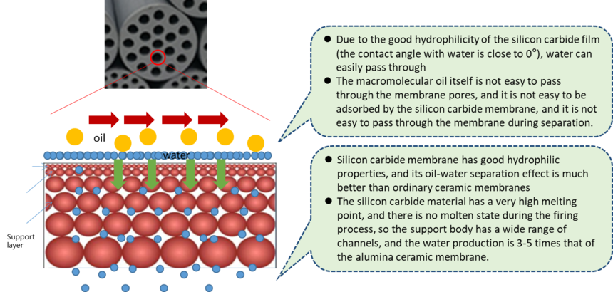
Silicon carbide ceramic powder has stable chemical properties (acid and alkali resistance, corrosion resistance, oxidation resistance), and it is hardly etched with any solvent at 1500°C.It has high thermal conductivity, low thermal expansion coefficient, strong hydrophilicity and good wear resistance, high hardness, Mohs hardness of 9.5, second only to the world's hardest diamond (10). The raw materials of the support layer, transition layer and separation layer of the silicon carbide film are all made of high-purity green silicon carbide (>99.5%) with the highest purity and best quality on the market, without adding any sintering aids. Therefore, it has almost all the characteristics of silicon carbide materials. SIC membranes can perform solid-liquid separation and oil-water separation through cross flow filtration in extreme environments (acid, alkali, high temperature, high concentration purification), SIC membrane oil-water separation:
Product Technical Parameters
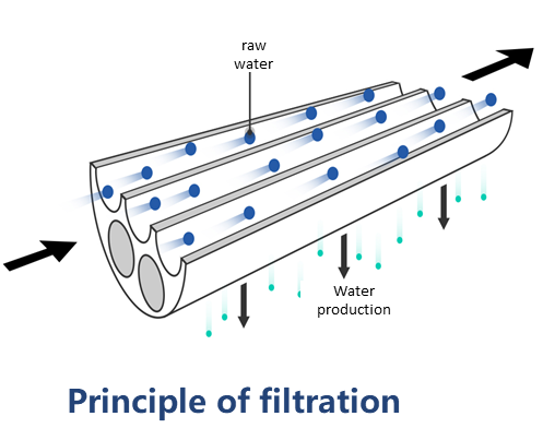
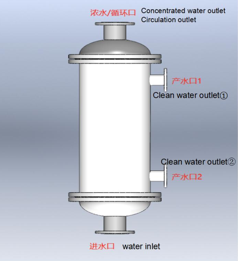
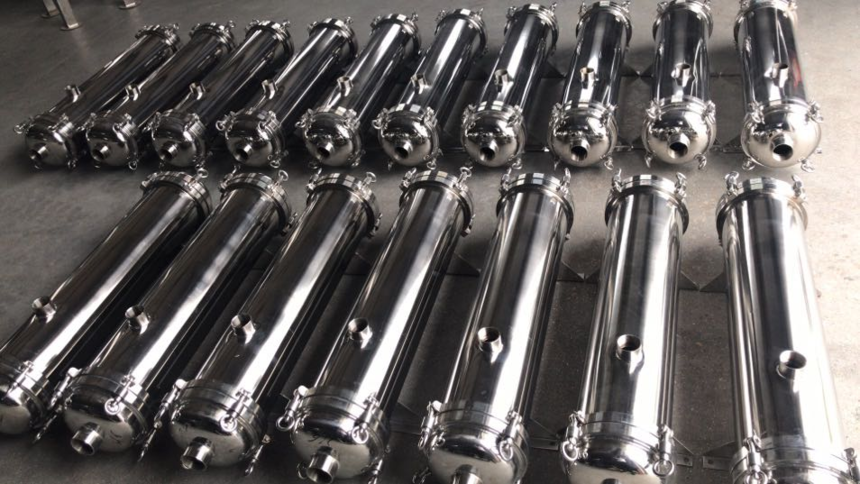
Membrane Support Filter - Ceramic Membrane Filter The materials for membrane filters typically include stainless steel, carbon steel lined with plastic, UPVC, and PPR. The typical number of membrane elements installed is 1, 5, 7, 19, 37, 61, or 91 pieces. Ceramic membranes operate in a cross-flow filtration mode. Influent water enters the ceramic membrane module, with a portion passing through the membrane surface to become permeate, while the remainder, carrying suspended solids and other impurities, exits the membrane module as concentrate. The discharged concentrate is repressurized and recycled back into the membrane module, maintaining a high flow velocity that generates shear force on the membrane surface, sweeping away suspended solids, oil, and other impurities intercepted by the membrane, thereby keeping the fouling layer relatively thin. When the influent water has a high suspended solids load (typically >50 NTU), a high permeate yield is required (>95%), or when there is a high resistance to fouling due to the presence of organics or oil, cross-flow operation is recommended. During cross-flow operation, a small stream of water (typically 10-100% of the filtration flow) is recirculated back to the front end of the system. A portion of this recirculated stream (5-20%) can be continuously discharged to prevent excessive suspended solids accumulation in the capillary channels.
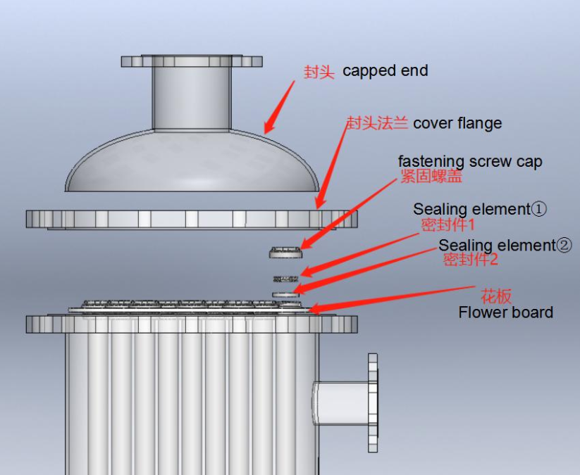
Product Detailed Description: 1.Structure Diagram and Installation Instructions for Single-Core Membrane Module The installation of a single-core membrane module can be carried out after the overall assembly of the equipment is completed, but it should be reasonably designed to prevent situations where assembly becomes impossible. The specific operation steps are as follows: Remove the upper and lower end caps, install a sealing component on the upper part of the membrane element, have one person insert it from above while another person assists in inserting it from below. After installing the sealing component at the lower part, reinstall the upper and lower end caps.
2.Structure diagram and installation instructions for multi-core membrane module
When installing ceramic membrane elements, first place the membrane housing cylinder flat on the ground, and install each membrane element in the corresponding installation position one by one. Insert the membrane elements into the holes of the membrane filter's distributor plate, with both ends exposed. Install Seal 1 and Seal 2 as shown in the diagram. Then, tighten the compression nuts and finally tighten the upper and lower flanges. Finally, use a lifting machine to install the membrane housing onto the equipment support, completing the installation of the membrane elements.
During the installation process, attention should be paid to the fragility of the ceramic membrane modules, and they should be handled with care. For multi-core membrane modules, ergonomic considerations should be taken into account in the design. Support should be provided for the upper and lower housing flanges, and sufficient maintenance space should be reserved around them. It is recommended to avoid lifting out the membrane housing for membrane component replacement as much as possible.
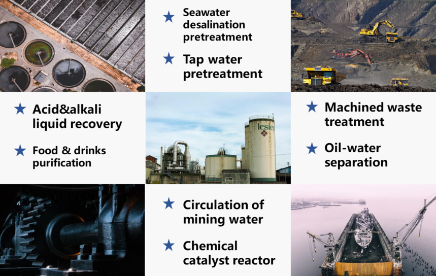
Product Advantages High water flux High mechanical strength Wear resistance Strong hydrophilicity Oil resistance Low operating pressure High-temperature resistance Low thermal expansion coefficient Product Applications Oil-water separation Mechanical waste treatment Chemical catalytic reactors Acid and alkali liquid recovery Seawater desalination pretreatment Tap water pretreatment Mine water circulation Food and beverage purification
|
||||||||||||||||||||||||||||||||||||||||||||||||||||||||||||||||||


